

G2D图像处理硬件调用和测试-基于米尔全志T113-i开发板

2024-04-09

2441

来源:米尔电子
本篇测评由电子工程世界的优秀测评者“jf_99374259”提供。
本文将介绍基于米尔电子MYD-YT113i开发板的G2D图像处理硬件调用和测试。
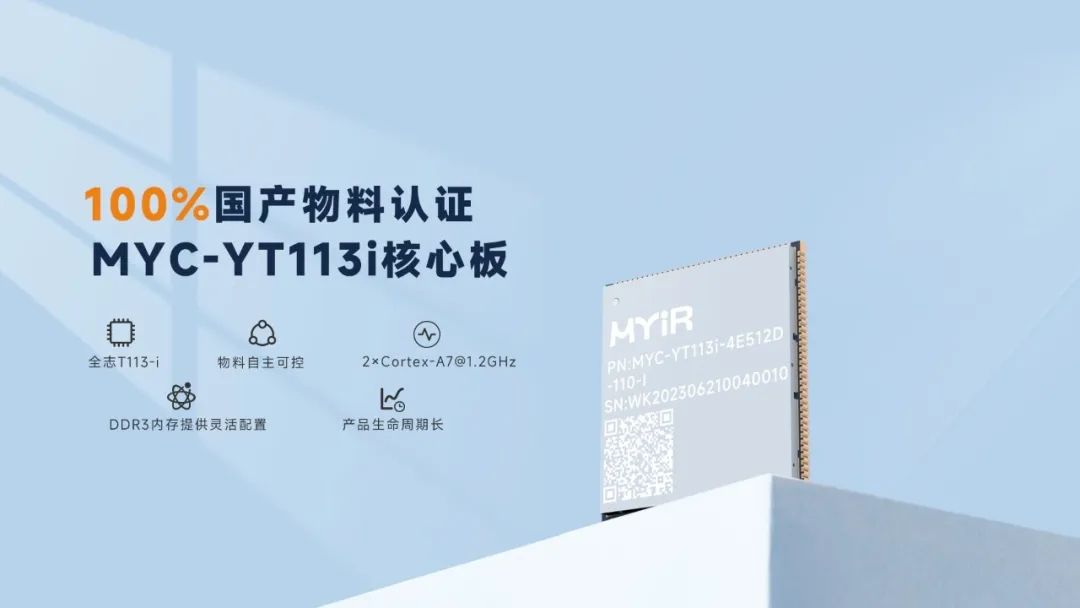
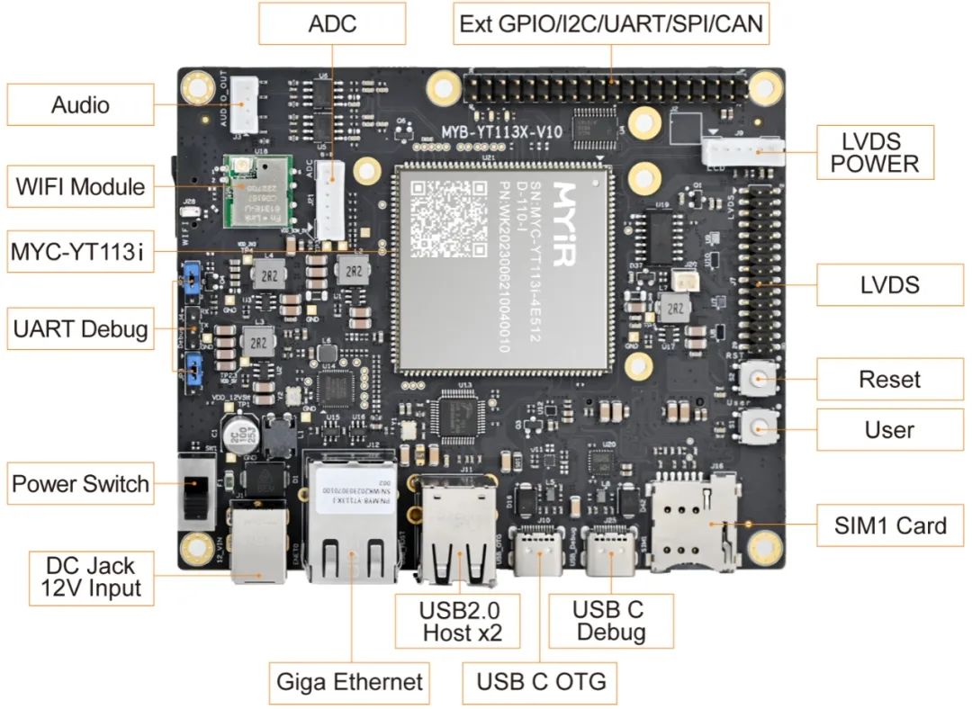
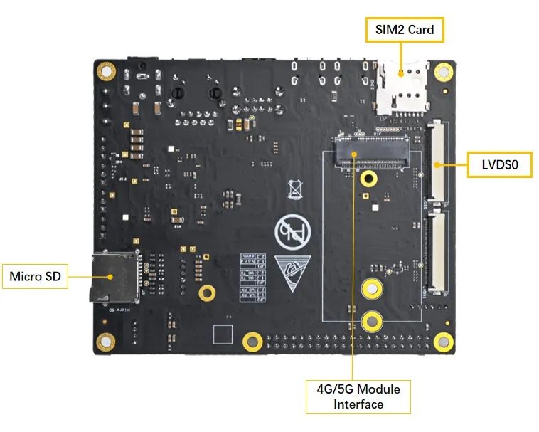
MYC-YT113i核心板及开发板
真正的国产核心板,100%国产物料认证
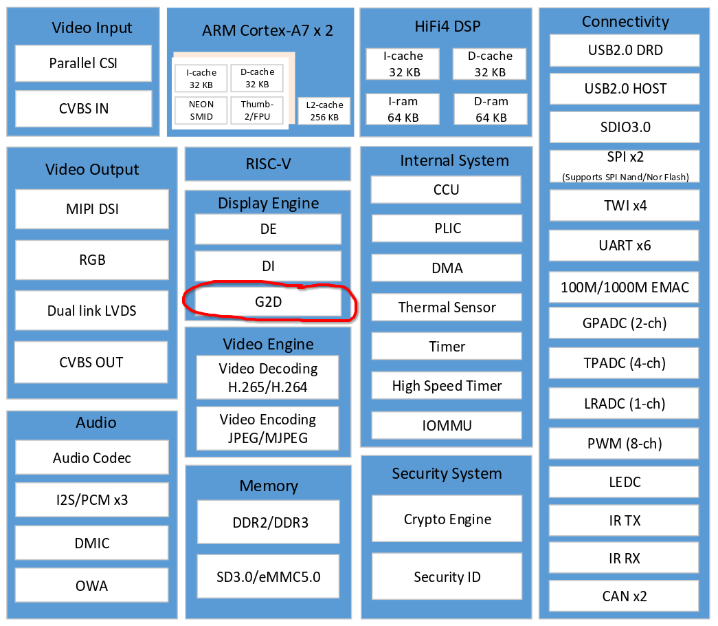
国产T113-i处理器配备2*Cortex-A7@1.2GHz ,RISC-V
外置DDR3接口、支持视频编解码器、HiFi4 DSP
接口丰富:视频采集接口、显示器接口、USB2.0 接口、CAN 接口、千兆以太网接口
工业级:-40℃~+85℃、尺寸37mm*39mm
邮票孔+LGA,140+50PIN
全志 T113-i 2D图形加速硬件支持情况
Supports layer size up to 2048 x 2048 pixels
Supports pre-multiply alpha image data
Supports color key
Supports two pipes Porter-Duff alpha blending
Supports multiple video formats 4:2:0, 4:2:2, 4:1:1 and multiple pixel formats (8/16/24/32 bits graphics
layer)Supports memory scan order option
Supports any format convert function
Supports 1/16× to 32× resize ratio
Supports 32-phase 8-tap horizontal anti-alias filter and 32-phase 4-tap vertical anti-alias filter
Supports window clip
Supports FillRectangle, BitBlit, StretchBlit and MaskBlit
Supports horizontal and vertical flip, clockwise 0/90/180/270 degree rotate for normal buffer
Supports horizontal flip, clockwise 0/90/270 degree rotate for LBC buffer
可以看到 g2d 硬件支持相当多的2D图像处理,包括颜色空间转换,分辨率缩放,图层叠加,旋转等
开发环境配置
基于C语言实现的YUV转RGB
这里复用之前T113-i JPG解码的函数
    void yuv420sp2rgb(const unsigned char* yuv420sp, int w, int h, unsigned char* rgb)
{
    const unsigned char* yptr = yuv420sp;
    const unsigned char* vuptr = yuv420sp + w * h;

    for (int y = 0; y < h; y += 2)
    {
       const unsigned char* yptr0 = yptr;
       const unsigned char* yptr1 = yptr + w;
       unsigned char* rgb0 = rgb;
       unsigned char* rgb1 = rgb + w * 3;

       int remain = w;

#define SATURATE_CAST_UCHAR(X) (unsigned char)::std::min(::std::max((int)(X), 0), 255);
       for (; remain > 0; remain -= 2)
       {
          // R = 1.164 * yy + 1.596 * vv
          // G = 1.164 * yy - 0.813 * vv - 0.391 * uu
          // B = 1.164 * yy              + 2.018 * uu

          // R = Y + (1.370705 * (V-128))
          // G = Y - (0.698001 * (V-128)) - (0.337633 * (U-128))
          // B = Y + (1.732446 * (U-128))

          // R = ((Y << 6) + 87.72512 * (V-128)) >> 6
          // G = ((Y << 6) - 44.672064 * (V-128) - 21.608512 * (U-128)) >> 6
          // B = ((Y << 6) + 110.876544 * (U-128)) >> 6

          // R = ((Y << 6) + 90 * (V-128)) >> 6
          // G = ((Y << 6) - 46 * (V-128) - 22 * (U-128)) >> 6
          // B = ((Y << 6) + 113 * (U-128)) >> 6

          // R = (yy + 90 * vv) >> 6
          // G = (yy - 46 * vv - 22 * uu) >> 6
          // B = (yy + 113 * uu) >> 6

          int v = vuptr[0] - 128;
          int u = vuptr[1] - 128;

          int ruv = 90 * v;
          int guv = -46 * v + -22 * u;
          int buv = 113 * u;

          int y00 = yptr0[0] << 6;
          rgb0[0] = SATURATE_CAST_UCHAR((y00 + ruv) >> 6);
          rgb0[1] = SATURATE_CAST_UCHAR((y00 + guv) >> 6);
          rgb0[2] = SATURATE_CAST_UCHAR((y00 + buv) >> 6);

          int y01 = yptr0[1] << 6;
          rgb0[3] = SATURATE_CAST_UCHAR((y01 + ruv) >> 6);
          rgb0[4] = SATURATE_CAST_UCHAR((y01 + guv) >> 6);
          rgb0[5] = SATURATE_CAST_UCHAR((y01 + buv) >> 6);

          int y10 = yptr1[0] << 6;
          rgb1[0] = SATURATE_CAST_UCHAR((y10 + ruv) >> 6);
          rgb1[1] = SATURATE_CAST_UCHAR((y10 + guv) >> 6);
          rgb1[2] = SATURATE_CAST_UCHAR((y10 + buv) >> 6);

          int y11 = yptr1[1] << 6;
          rgb1[3] = SATURATE_CAST_UCHAR((y11 + ruv) >> 6);
          rgb1[4] = SATURATE_CAST_UCHAR((y11 + guv) >> 6);
          rgb1[5] = SATURATE_CAST_UCHAR((y11 + buv) >> 6);

          yptr0 += 2;
          yptr1 += 2;
          vuptr += 2;
          rgb0 += 6;
          rgb1 += 6;
       }
#undef SATURATE_CAST_UCHAR

       yptr += 2 * w;
       rgb += 2 * 3 * w;
    }
}
基于ARM neon指令集优化的YUV转RGB
考虑到armv7编译器的自动neon优化能力较差,这里针对性的编写 arm neon inline assembly 实现YUV2RGB内核部分,达到最优化的性能,榨干cpu性能
    void yuv420sp2rgb_neon(const unsigned char* yuv420sp, int w, int h, unsigned char* rgb)
{
    const unsigned char* yptr = yuv420sp;
    const unsigned char* vuptr = yuv420sp + w * h;

#if __ARM_NEON
    uint8x8_t _v128 = vdup_n_u8(128);
    int8x8_t _v90 = vdup_n_s8(90);
    int8x8_t _v46 = vdup_n_s8(46);
    int8x8_t _v22 = vdup_n_s8(22);
    int8x8_t _v113 = vdup_n_s8(113);
#endif // __ARM_NEON

    for (int y = 0; y < h; y += 2)
    {
       const unsigned char* yptr0 = yptr;
       const unsigned char* yptr1 = yptr + w;
       unsigned char* rgb0 = rgb;
       unsigned char* rgb1 = rgb + w * 3;

#if __ARM_NEON
       int nn = w >> 3;
       int remain = w - (nn << 3);

#else
       int remain = w;
#endif // __ARM_NEON

#if __ARM_NEON
#if __aarch64__
       for (; nn > 0; nn--)
       {
          int16x8_t _yy0 = vreinterpretq_s16_u16(vshll_n_u8(vld1_u8(yptr0), 6));
          int16x8_t _yy1 = vreinterpretq_s16_u16(vshll_n_u8(vld1_u8(yptr1), 6));

          int8x8_t _vvuu = vreinterpret_s8_u8(vsub_u8(vld1_u8(vuptr), _v128));
          int8x8x2_t _vvvvuuuu = vtrn_s8(_vvuu, _vvuu);
          int8x8_t _vv = _vvvvuuuu.val[0];
          int8x8_t _uu = _vvvvuuuu.val[1];

          int16x8_t _r0 = vmlal_s8(_yy0, _vv, _v90);
          int16x8_t _g0 = vmlsl_s8(_yy0, _vv, _v46);
          _g0 = vmlsl_s8(_g0, _uu, _v22);
          int16x8_t _b0 = vmlal_s8(_yy0, _uu, _v113);

          int16x8_t _r1 = vmlal_s8(_yy1, _vv, _v90);
          int16x8_t _g1 = vmlsl_s8(_yy1, _vv, _v46);
          _g1 = vmlsl_s8(_g1, _uu, _v22);
          int16x8_t _b1 = vmlal_s8(_yy1, _uu, _v113);

          uint8x8x3_t _rgb0;
          _rgb0.val[0] = vqshrun_n_s16(_r0, 6);
          _rgb0.val[1] = vqshrun_n_s16(_g0, 6);
          _rgb0.val[2] = vqshrun_n_s16(_b0, 6);

          uint8x8x3_t _rgb1;
          _rgb1.val[0] = vqshrun_n_s16(_r1, 6);
          _rgb1.val[1] = vqshrun_n_s16(_g1, 6);
          _rgb1.val[2] = vqshrun_n_s16(_b1, 6);

          vst3_u8(rgb0, _rgb0);
          vst3_u8(rgb1, _rgb1);

          yptr0 += 8;
          yptr1 += 8;
          vuptr += 8;
          rgb0 += 24;
          rgb1 += 24;
       }
#else
       if (nn > 0)
       {
          asm volatile(
             "0:                             n"
             "pld        [%3, #128]          n"
             "vld1.u8    {d2}, [%3]!         n"
             "vsub.s8    d2, d2, %12         n"
             "pld        [%1, #128]          n"
             "vld1.u8    {d0}, [%1]!         n"
             "pld        [%2, #128]          n"
             "vld1.u8    {d1}, [%2]!         n"
             "vshll.u8   q2, d0, #6          n"
             "vorr       d3, d2, d2          n"
             "vshll.u8   q3, d1, #6          n"
             "vorr       q9, q2, q2          n"
             "vtrn.s8    d2, d3              n"
             "vorr       q11, q3, q3         n"
             "vmlsl.s8   q9, d2, %14         n"
             "vorr       q8, q2, q2          n"
             "vmlsl.s8   q11, d2, %14        n"
             "vorr       q10, q3, q3         n"
             "vmlal.s8   q8, d2, %13         n"
             "vmlal.s8   q2, d3, %16         n"
             "vmlal.s8   q10, d2, %13        n"
             "vmlsl.s8   q9, d3, %15         n"
             "vmlal.s8   q3, d3, %16         n"
             "vmlsl.s8   q11, d3, %15        n"
             "vqshrun.s16 d24, q8, #6        n"
             "vqshrun.s16 d26, q2, #6        n"
             "vqshrun.s16 d4, q10, #6        n"
             "vqshrun.s16 d25, q9, #6        n"
             "vqshrun.s16 d6, q3, #6         n"
             "vqshrun.s16 d5, q11, #6        n"
             "subs       %0, #1              n"
             "vst3.u8    {d24-d26}, [%4]!    n"
             "vst3.u8    {d4-d6}, [%5]!      n"
             "bne        0b                  n"
             : "=r"(nn),    // %0
             "=r"(yptr0), // %1
             "=r"(yptr1), // %2
             "=r"(vuptr), // %3
             "=r"(rgb0),  // %4
             "=r"(rgb1)   // %5
             : "0"(nn),
             "1"(yptr0),
             "2"(yptr1),
             "3"(vuptr),
             "4"(rgb0),
             "5"(rgb1),
             "w"(_v128), // %12
             "w"(_v90),  // %13
             "w"(_v46),  // %14
             "w"(_v22),  // %15
             "w"(_v113)  // %16
             : "cc", "memory", "q0", "q1", "q2", "q3", "q8", "q9", "q10", "q11", "q12", "d26");
          }

#endif // __aarch64__
#endif // __ARM_NEON

#define SATURATE_CAST_UCHAR(X) (unsigned char)::std::min(::std::max((int)(X), 0), 255);
       for (; remain > 0; remain -= 2)
       {
          // R = 1.164 * yy + 1.596 * vv
          // G = 1.164 * yy - 0.813 * vv - 0.391 * uu
          // B = 1.164 * yy              + 2.018 * uu

          // R = Y + (1.370705 * (V-128))
          // G = Y - (0.698001 * (V-128)) - (0.337633 * (U-128))
          // B = Y + (1.732446 * (U-128))

          // R = ((Y << 6) + 87.72512 * (V-128)) >> 6
          // G = ((Y << 6) - 44.672064 * (V-128) - 21.608512 * (U-128)) >> 6
          // B = ((Y << 6) + 110.876544 * (U-128)) >> 6

          // R = ((Y << 6) + 90 * (V-128)) >> 6
          // G = ((Y << 6) - 46 * (V-128) - 22 * (U-128)) >> 6
          // B = ((Y << 6) + 113 * (U-128)) >> 6

          // R = (yy + 90 * vv) >> 6
          // G = (yy - 46 * vv - 22 * uu) >> 6
          // B = (yy + 113 * uu) >> 6

          int v = vuptr[0] - 128;
          int u = vuptr[1] - 128;

          int ruv = 90 * v;
          int guv = -46 * v + -22 * u;
          int buv = 113 * u;

          int y00 = yptr0[0] << 6;
          rgb0[0] = SATURATE_CAST_UCHAR((y00 + ruv) >> 6);
          rgb0[1] = SATURATE_CAST_UCHAR((y00 + guv) >> 6);
          rgb0[2] = SATURATE_CAST_UCHAR((y00 + buv) >> 6);

          int y01 = yptr0[1] << 6;
          rgb0[3] = SATURATE_CAST_UCHAR((y01 + ruv) >> 6);
          rgb0[4] = SATURATE_CAST_UCHAR((y01 + guv) >> 6);
          rgb0[5] = SATURATE_CAST_UCHAR((y01 + buv) >> 6);

          int y10 = yptr1[0] << 6;
          rgb1[0] = SATURATE_CAST_UCHAR((y10 + ruv) >> 6);
          rgb1[1] = SATURATE_CAST_UCHAR((y10 + guv) >> 6);
          rgb1[2] = SATURATE_CAST_UCHAR((y10 + buv) >> 6);

          int y11 = yptr1[1] << 6;
          rgb1[3] = SATURATE_CAST_UCHAR((y11 + ruv) >> 6);
          rgb1[4] = SATURATE_CAST_UCHAR((y11 + guv) >> 6);
          rgb1[5] = SATURATE_CAST_UCHAR((y11 + buv) >> 6);

          yptr0 += 2;
          yptr1 += 2;
          vuptr += 2;
          rgb0 += 6;
          rgb1 += 6;
       }
#undef SATURATE_CAST_UCHAR

       yptr += 2 * w;
       rgb += 2 * 3 * w;
    }
}
基于G2D图形硬件的YUV转RGB
我们先实现 dmaion buffer 管理器,参考
这里贴的代码省略了异常错误处理的逻辑,有个坑是 linux-4.9 和 linux-5.4 用法不一样,米尔电子的这个T113-i系统是linux-5.4,所以不兼容4.9内核的ioctl用法习惯
    struct ion_memory
{
    size_t size;
    int fd;
    void* virt_addr;
    unsigned int phy_addr;
};

class ion_allocator
{
public:
    ion_allocator();
    ~ion_allocator();

    int open();
    void close();

    int alloc(size_t size, struct ion_memory* mem);
    int free(struct ion_memory* mem);

    int flush(struct ion_memory* mem);

public:
    int ion_fd;
    int cedar_fd;
};

    ion_allocator::ion_allocator()
{
    ion_fd = -1;
    cedar_fd = -1;
}

ion_allocator::~ion_allocator()
{
    close();
}

int ion_allocator::open()
{
    close();

    ion_fd = ::open("/dev/ion", O_RDWR);
    cedar_fd = ::open("/dev/cedar_dev", O_RDONLY);

    ioctl(cedar_fd, IOCTL_ENGINE_REQ, 0);

    return 0;
}

void ion_allocator::close()
{
    if (cedar_fd != -1)
    {
       ioctl(cedar_fd, IOCTL_ENGINE_REL, 0);
       ::close(cedar_fd);
       cedar_fd = -1;
    }

    if (ion_fd != -1)
    {
       ::close(ion_fd);
       ion_fd = -1;
    }
}

int ion_allocator::alloc(size_t size, struct ion_memory* mem)
{
    struct aw_ion_new_alloc_data alloc_data;
    alloc_data.len = size;
    alloc_data.heap_id_mask = AW_ION_SYSTEM_HEAP_MASK;
    alloc_data.flags = AW_ION_CACHED_FLAG | AW_ION_CACHED_NEEDS_SYNC_FLAG;
    alloc_data.fd = 0;
    alloc_data.unused = 0;
    ioctl(ion_fd, AW_ION_IOC_NEW_ALLOC, &alloc_data);

    void* virt_addr = mmap(NULL, size, PROT_READ|PROT_WRITE, MAP_SHARED, alloc_data.fd, 0);

    struct aw_user_iommu_param iommu_param;
    iommu_param.fd = alloc_data.fd;
    iommu_param.iommu_addr = 0;
    ioctl(cedar_fd, IOCTL_GET_IOMMU_ADDR, &iommu_param);

    mem->size = size;
    mem->fd = alloc_data.fd;
    mem->virt_addr = virt_addr;
    mem->phy_addr = iommu_param.iommu_addr;

    return 0;
}

int ion_allocator::free(struct ion_memory* mem)
{
    if (mem->fd == -1)
        return 0;

        struct aw_user_iommu_param iommu_param;
        iommu_param.fd = mem->fd;
        ioctl(cedar_fd, IOCTL_FREE_IOMMU_ADDR, &iommu_param);

        munmap(mem->virt_addr, mem->size);

        ::close(mem->fd);

        mem->size = 0;
        mem->fd = -1;
        mem->virt_addr = 0;
        mem->phy_addr = 0;

        return 0;
}

int ion_allocator::flush(struct ion_memory* mem)
{
        struct dma_buf_sync sync;
        sync.flags = DMA_BUF_SYNC_END | DMA_BUF_SYNC_RW;
        ioctl(mem->fd, DMA_BUF_IOCTL_SYNC, &sync);

        return 0;
}
然后再实现 G2D图形硬件 YUV转RGB 的转换器
提前分配好YUV和RGB的dmaion buffer
将YUV数据拷贝到dmaion buffer,flush cache完成同步
配置转换参数,ioctl调用G2D_CMD_BITBLT_H完成转换
flush cache完成同步,从dmaion buffer拷贝出RGB数据
释放dmaion buffer
    // 步骤1
ion_allocator ion;
ion.open();

struct ion_memory yuv_ion;
ion.alloc(rgb_size, &rgb_ion);

struct ion_memory rgb_ion;
ion.alloc(yuv_size, &yuv_ion);

int g2d_fd = ::open("/dev/g2d", O_RDWR);

// 步骤2
memcpy((unsigned char*)yuv_ion.virt_addr, yuv420sp, yuv_size);
ion.flush(&yuv_ion);

// 步骤3
g2d_blt_h blit;
memset(&blit, 0, sizeof(blit));

blit.flag_h = G2D_BLT_NONE_H;

blit.src_image_h.format = G2D_FORMAT_YUV420UVC_V1U1V0U0;
blit.src_image_h.width = width;
blit.src_image_h.height = height;
blit.src_image_h.align[0] = 0;
blit.src_image_h.align[1] = 0;
blit.src_image_h.clip_rect.x = 0;
blit.src_image_h.clip_rect.y = 0;
blit.src_image_h.clip_rect.w = width;
blit.src_image_h.clip_rect.h = height;
blit.src_image_h.gamut = G2D_BT601;
blit.src_image_h.bpremul = 0;
blit.src_image_h.mode = G2D_PIXEL_ALPHA;
blit.src_image_h.use_phy_addr = 0;
blit.src_image_h.fd = yuv_ion.fd;

blit.dst_image_h.format = G2D_FORMAT_RGB888;
blit.dst_image_h.width = width;
blit.dst_image_h.height = height;
blit.dst_image_h.align[0] = 0;
blit.dst_image_h.clip_rect.x = 0;
blit.dst_image_h.clip_rect.y = 0;
blit.dst_image_h.clip_rect.w = width;
blit.dst_image_h.clip_rect.h = height;
blit.dst_image_h.gamut = G2D_BT601;
blit.dst_image_h.bpremul = 0;
blit.dst_image_h.mode = G2D_PIXEL_ALPHA;
blit.dst_image_h.use_phy_addr = 0;
blit.dst_image_h.fd = rgb_ion.fd;

ioctl(g2d_fd, G2D_CMD_BITBLT_H, &blit);

// 步骤4
ion.flush(&rgb_ion);
memcpy(rgb, (const unsigned char*)rgb_ion.virt_addr, rgb_size);

// 步骤5
ion.free(&rgb_ion);
ion.free(&yuv_ion);
ion.close();
::close(g2d_fd);
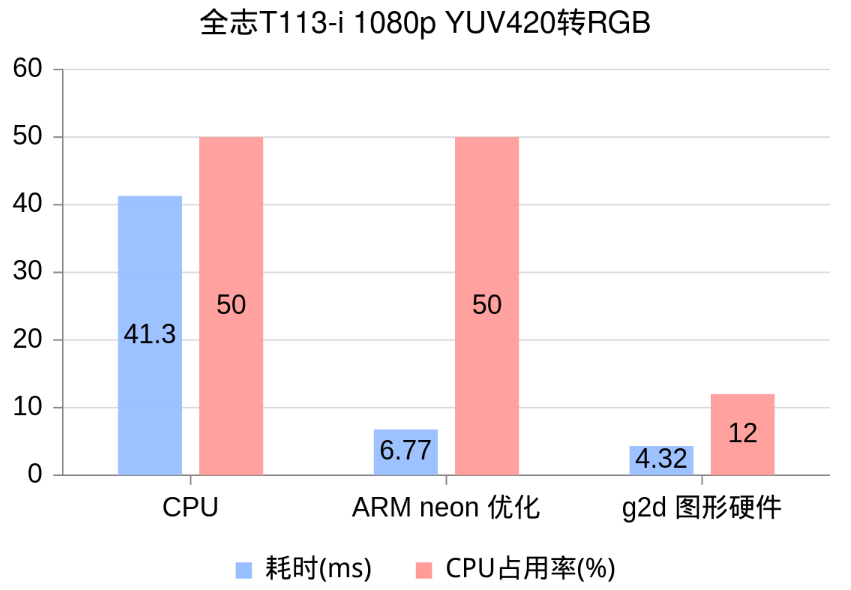
G2D图像硬件YUV转RGB测试
考虑到dmaion buffer分配和释放都比较耗时,我们提前做好,循环调用步骤3的G2D转换,统计耗时,并在top工具中查看CPU占用率
    sh-4.4# LD_LIBRARY_PATH=. ./g2dtest
INFO   : cedarc <CedarPluginVDInit:84>: register mjpeg decoder success!
this device is not whitelisted for jpeg decoder cvi
this device is not whitelisted for jpeg decoder cvi
this device is not whitelisted for jpeg decoder cvi
this device is not whitelisted for jpeg encoder rkmpp
INFO   : cedarc <log_set_level:43>: Set log level to 5 from /vendor/etc/cedarc.conf
ERROR  : cedarc <DebugCheckConfig:316>: now cedarc log level:5
ERROR  : cedarc <VideoEncCreate:241>: now cedarc log level:5
yuv420sp2rgb 46.61
yuv420sp2rgb 42.04
yuv420sp2rgb 41.32
yuv420sp2rgb 42.06
yuv420sp2rgb 41.69
yuv420sp2rgb 42.05
yuv420sp2rgb 41.29
yuv420sp2rgb 41.30
yuv420sp2rgb 42.14
yuv420sp2rgb 41.33
yuv420sp2rgb_neon 10.57
yuv420sp2rgb_neon 7.21
yuv420sp2rgb_neon 6.77
yuv420sp2rgb_neon 8.31
yuv420sp2rgb_neon 7.60
yuv420sp2rgb_neon 6.80
yuv420sp2rgb_neon 6.77
yuv420sp2rgb_neon 7.01
yuv420sp2rgb_neon 7.11
yuv420sp2rgb_neon 7.06
yuv420sp2rgb_g2d 4.32
yuv420sp2rgb_g2d 4.69
yuv420sp2rgb_g2d 4.56
yuv420sp2rgb_g2d 4.57
yuv420sp2rgb_g2d 4.52
yuv420sp2rgb_g2d 4.54
yuv420sp2rgb_g2d 4.52
yuv420sp2rgb_g2d 4.58
yuv420sp2rgb_g2d 4.60
yuv420sp2rgb_g2d 4.67
可以看到 ARM neon 的优化效果非常明显,而使用G2D图形硬件能获得进一步加速,并且能显著降低CPU占用率!
| 耗时(ms) | CPU占用率(%) | |
|---|---|---|
| C | 41.30 | 50 |
| neon | 6.77 | 50 |
| g2d | 4.32 | 12 |
转换结果对比和分析
C和neon的转换结果完全一致,但是g2d转换后的图片有明显的色差


G2D图形硬件只支持 G2D_BT601,G2D_BT709,G2D_BT2020 3种YUV系数,而JPG所使用的YUV系数是改版BT601,因此产生了色差
从g2d内核驱动中也可以得知,暂时没有方法为g2d设置自定义的YUV系数,g2d不适合用于JPG的编解码,但依然适合摄像头和视频编解码的颜色空间转换

2026-03-19
新品!瑞萨RZ/T2H驱控一体单芯、多轴实时控制,助力工业以太网
米尔电子发布基于瑞萨高端MPU处理器RZ/T2H的CPU模组-MYC-YT2HX核心板及开发板。该产品在前代产品RZ的基础上进行了全面升级,RZ/T2H以其强大的硬件支持、全面的软件开发工具、丰富的工业以太网协议和安全解决方案,以及多操作系统的灵活配置,为客户提供了一个全方位、高效率的开发环境。MYC-YT2HX核心板的推出,旨在解决工业数字化进程中对高性能产品升级以及对复杂网络控制的需求,如工业
2026-03-12
RK3576 + ROS2 SLAM建图与导航实战
前言文档定位与目标读者本文档面向具备一定ROS基础、希望深入理解并在实际项目中部署ROS2 Humble + SLAM Toolbox + Nav2完整建图与导航系统的机器人工程师。我们将从零开始,基于米尔RK3576开发板逐步构建一个功能完备的自主移动机器人系统,涵盖环境搭建、机器人建模、SLAM建图、自主导航以及生产级系统的优化与排错。为什么选择SLAM Toolbox + Nav2?在ROS
2026-03-12
米尔亮相德国嵌入式展2026 Embedded World
2026年3月10日,全球嵌入式系统领域的年度盛会——Embedded World在德国纽伦堡展览中心盛大启幕。作为领先的嵌入式处理器模组厂商,米尔电子携全系列嵌入式核心板、开发板及创新解决方案重磅亮相,与来自全球40多个国家的1100余家展商、32000余名专业观众共赴这场技术盛宴。Embedded World自创办以来,已成为全球规模最大、影响力最深远的嵌入式系统展览会,聚焦嵌入式硬件系统、软
2026-03-06
新品!高能效,低功耗,TI AM62L经典再进化
众所周知,TI经典工业MPUAM335x曾引领行业风潮,而2023年TI发布64位MPU通用工业处理器平台AM62x,为AM335x用户提供了无缝升级路径,实现更高性能的功能需求。AM62L作为AM62x家族的降本之作,在性能和资源上做了裁剪,成本上做了优化,延续AM62x的经典基因,以更低门槛推进低功耗、高能效的工业处理器普及,助力开发者以高效方案应对多样化的需求。米尔与TI再联手,推出基于TI
2026-03-06
爆火的OpenClaw! 告别云端,米尔RK3576本地部署
1.概述基于最近爆火的OpenClaw项目,本文将在MYD-LR3576开发板上部署OpenClaw ,并接入飞书机器人,实现本地自托管 AI 助手。1.1.硬件资源部署端:米尔基于RK3576核心板开发板(MYD-LR3576)、外接鼠标、键盘和屏幕图:米尔基于RK3576系列核心板开发板调试端:PC电脑(Windows系统、Ubuntu系统皆可)1.2. 软件资源MYD-LR3576开发板使用
2026-02-11
【干货】米尔T153开发板AD7616高速ADC采集系统详解
PART 01项目概述1.1 技术背景米尔MYD-YT153开发板搭载全志T153处理器,提供LocalBus(LBC)并行总线接口,适合连接高速外设。AD7616是ADI公司推出的16位高精度并行ADC,具有16通道差分输入,广泛应用于工业数据采集、仪器仪表等领域。1.2 项目目标验证MYD-YT153 LocalBus与AD7616的硬件兼容性提供完整的软件驱动实现方案评估系统在实际应用中的性
2026-01-29
新法规欧标AC桩一站式技术实现方案
面对欧盟Delegated Regulation (EU) 2025/656条例设定的明确技术路线与2027年强制生效节点,开发符合 EN ISO 15118-20:2022 标准的下一代智能交流充电桩,已成为产品进入欧洲市场的唯一路径。这意味着,传统PWM通信方式即将淘汰,全面转向基于 GreenPHY电力线载波(PLC)的高层通信,并强制集成即插即充(PnC)与车辆到电网(V2G)能力。01硬
2026-01-22
看过来,米尔RK3576 NPU方案你用对了吗?
本文基于米尔MYD-LR3576开发板,详细记录了如何利用500万像素USB摄像头实现640×640分辨率的YOLO5s目标检测,并将结果实时输出至1080P屏幕的全流程。通过系统级的软硬件协同优化,最终将端到端延迟控制在40ms以内,实现了 20FPS的稳定实时检测性能。文章重点剖析了摄像头特性分析、显示通路选择、RGA硬件加速、RKNN NPU集成等关键技术环节,为嵌入式AI视觉系统的开发与调
2026-01-22
全场景工控与网关解决方案:从入门到旗舰的一站式选型
在工业自动化与物联网向深度智能迈进的浪潮中,工业设备对成本控制、运行可靠性及智能算力的要求正持续攀升。无论是追求极致性价比的基础工控终端,还是需要强劲算力支撑的AIoT边缘节点,开发者都在为不同场景寻觅适配的“工业之芯”。对此,我们基于MYC-YR3506、MYC-LT536、MYC-LR3576三款核心板,打造了覆盖低、中、高端全场景的工业控制与网关解决方案,以一站式选型体系,助力工业产品实现“
2026-01-15
当国产芯遇上机器人:RK3576的ROS2奇幻之旅
当RK3576的强劲“大脑”(四核A72+四核A53)与强大的GPU、VPU、NPU加速模块相遇,一场高性价比的机器人开发革命正在悄然发生。我们成功将完整的Ubuntu 22.04与ROS2 Humble生态系统,完美移植到了这颗国产芯片上。一个稳定、全功能的机器人软件开发平台已经就绪,现在就来一起探索它的强大魅力!一、系统启动与基础性能展示1.硬件平台简介开发板:MYD-LR3576存储:eMM